• Ernie Ball
  • MusicMan
  • Sterling by MusicMan

PeteDuBaldo

Well-known member
Joined
Jul 16, 2004
Messages
10,183
Location
Central Connecticut (Manchester) USA
Since this JP coil split / full humbuckers / push-pull topic has come up a lot lately here is a quick diagram of how to wire it up!

Good luck...

For use with the old 6-sided "green" pcb
JP6-push-pull-mod.jpg


For use with the new rectangular "black" pcb
John-Petrucci-JP-Toggle-Push-Pull-Wiring-Diagram-EP1111-DP1200PP.jpg
 
Last edited:

Benji Peterson

Well-known member
Joined
May 2, 2011
Messages
840
Location
Joplin, MO
Since this JP coil split / full humbuckers / push-pull topic has come up a lot lately here is a quick diagram of how to wire it up!

Good luck...

large.jpg


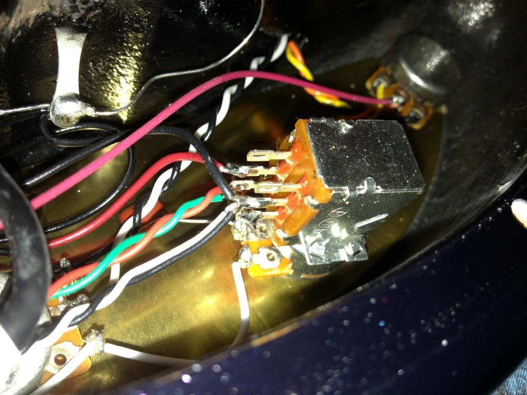
I'm thinking seriously about doing this for my JPXI and JPXII but I'm not sure the diagram matches the actual wiring on my JPXI (which is stock and is coil tap in up position). Take a look:


The wiring in the diagram doesn't seem to be accurate but I'm sure it's some kind of simple error. Or am I just missing something?
 

PeteDuBaldo

Well-known member
Joined
Jul 16, 2004
Messages
10,183
Location
Central Connecticut (Manchester) USA
Ben, it's the same but different, and either way works!

The location for the wires from the pickups and the wires to the switch are swapped, but complete the circuit in exactly the same way. (the signal in my diagram goes from outer pad to inner pad, EB wiring has signal flow from inner pad to outer pad)

If you want to switch the push/pull configuration simply relocate the paired wires to the unused pads on the push/pull (what appear as the "top" pads in your photo).
 

chrisallen

Well-known member
Joined
Oct 12, 2006
Messages
92
hey guys, just got a JP12 bali burst from GC - i had to have that color!

the new default for JPs is to have full humbuckers in the middle position with the tone knob down/pushed, and the coil split with the tone knob up/pulled.

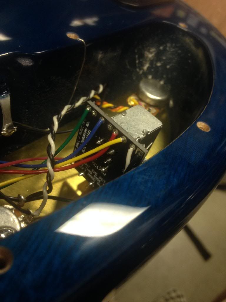
i'd rather have it like the classic JP guitars where the coil tap is down. i found this thread, but the push/pull knob is different in my guitar - it seems to have a specific solder point for each wire, instead of needing to pair wires together - 8 points total. here's a picture of the default wiring:

DEQlxwOUbXitiA1c


i emailed support and they can't provide me any information on this sort of "mod"...

so i experimented a bit. i moved the blue wire one slot to the left and the yellow to the left of the red. with this, i got the coil-tap in the middle position, but the push/pull didn't affect anything, and i think i lost a coil in my neck pickup or something haha.

would anyone know how to change the wiring for what i want?

if possible, even better would be the mod talked about here:

http://forums.ernieball.com/music-m...s-wiring-mod-add-three-additional-sounds.html

any ideas? thanks guys!
 

chrisallen

Well-known member
Joined
Oct 12, 2006
Messages
92
so... i, um, figured it out!

i assumed that the vacant holes on the top of that push/pull pot were the way to go, but unfortunately they aren't. if you look closely (barely see it in my picture) there are markings that show the hole connects to one of the 6 poles for the push/pull part of the knob. the blue connects to the middle "left" pole (in this view) and the yellow connects to the middle "right."

doing a little research i learned that the middle poles are always in use, so that clued me to not move those.

earlier i disconnected everything except the single black and white wires and i had basic full pickup mode, so i knew not to disconnect those.

so i was left with the green and red.

if you look at the green, it connects to the bottom "left" pole. the hole where the red is actually doesn't seem to connect to anything, but maybe it just can't be seen.

with that research, i learned that the "bottom" poles in this picture view are enabled when the switch is pulled up. pulled is when i got the coil split. i wanted that reversed so that means i have to move the green and red to the "top" poles so when the switch is down, it would split.

again, it seems like the vacant holes in my picture aren't connected to anything because when i put the red and green cables to them, all i got were full humbuckers, no effect of the push pull. (i would REALLY love someone who knows what they are doing to confirm this haha!)

so that lead me to try and hardwire the green to the "top left" pole and the red to the "top right" pole. and BAM it works exactly how i want it to! just like every EBMM JP i bought before, it coil taps when down, and full humbucker when up.

the other thread i linked to has more to do with the pickup select switch, so nevermind on that.

does anyone know when and why the default coil tap was changed? does JP not use the coil tap middle position anymore? and i think it's technically called parallel right?
 

beej

Moderator
Joined
Aug 16, 2004
Messages
12,240
Location
Toronto, Canada
Yep- you have to swap the bottom & top set of poles to change when the split is engaged, good that you sorted it out.
 

chrisallen

Well-known member
Joined
Oct 12, 2006
Messages
92
Yep- you have to swap the bottom & top set of poles to change when the split is engaged, good that you sorted it out.

i didn't think i'd have to solder directly to the poles, as there is that new circuit board. but alas, i do!
 

Castelmonio

Member
Joined
Jun 16, 2017
Messages
5
Many thanks for the doc. I suppose that explanation is valid for the inner coils, but if I want is the outside coils what cables should I re-solder?
 

DCStrat

New member
Joined
Oct 8, 2018
Messages
4
Has anyone modified a JP15 to coil split in all three positions instead of just middle?
 
Top Bottom