Hello... I am having a hell of a time getting this mod going. I have searched for diagrams and have followed the thread that had detailed pictures but I still cant get it right. I have an old JP6 with out the peizo pickup. I installed the push pull pot but..with the pot down I get bridge, The two inner coils and neck.. With it pulled I get bridge(inner coil) the two inner coils, and neck inner coil. What am I doing wrong.. I can not get the two full humbuckers going at the same time with the pot pushed and the 3 way in the center position. The center position for the pot pulled or pushed is the same.. the two inner coils.. Please help ...a diagram would be great as well... Thanks in advance!!

You are using an out of date browser. It may not display this or other websites correctly.
You should upgrade or use an alternative browser.
You should upgrade or use an alternative browser.
- Thread starter acidsid75
- Start date
beej
Moderator
Not sure which diagram you followed, but that's what a lot of people wanted- split HBs in the center position, with the push/pull up or down. So you may have wired it up correctly.
I would contact MM customer service on Monday and ask them for the JP schematic with the push/pull, and start from there.
Btw, no, it shouldn't matter what kind of push/pull you're using.
I would contact MM customer service on Monday and ask them for the JP schematic with the push/pull, and start from there.
Btw, no, it shouldn't matter what kind of push/pull you're using.
Thanks for the reply.. I sent them an email this morning. I don't really use that position but the way I am it messes with me knowing it does not work correctly. By the way I followed this tread.... http://forums.ernieball.com/music-m...sh-pull-pot-mod-installed.html.....Everything look like the pictures..but I get no double humbuckers in the pushed center position.. Thanks again!!
PeteDuBaldo
Well-known member
PeteDuBaldo
Well-known member
Thank you ..I saw that.. but he was confused .. do all the legs have connections..cuz in the diagrams we saw only the middle legs had connections
No, only 4 of the 6 lugs are used in the JP BFR push/pull switching. Also make sure the regular connections on the pot itself are done as normal.
Posted from my phone with Tapatalk!
Dr.Strangenote
Well-known member
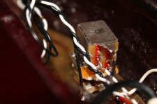
Make sure that the bottom lugs are grounded.
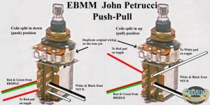
Here is the stock BFR wiring with a push/pull.

In the mod thread, he's doing it just a little different, and I've done this too, it sounds great! I'll point out the differences zoomed in at the switch, verse what EBMM wiring diagram shows above.
Here is the stock BFR wiring with a push/pull.
In the mod thread, he's doing it just a little different, and I've done this too, it sounds great! I'll point out the differences zoomed in at the switch, verse what EBMM wiring diagram shows above.
Dr.Strangenote
Well-known member
I've wired it this way (above), and push/pull gets all inner coils, Bridge (inner) -- Bridge/Neck(inner) -- Neck(inner). Pushed is stock wiring, Full Humbucker Bridge -- Bridge/Neck -- Full Neck. I hope this helps..
This is the mod thread found here: (link in OP's thread isn't reachable)
http://forums.ernieball.com/music-man-guitars/37794-john-petrucci-6-push-pull-pot-mod-installed.html
This is the mod thread found here: (link in OP's thread isn't reachable)
http://forums.ernieball.com/music-man-guitars/37794-john-petrucci-6-push-pull-pot-mod-installed.html
Last edited:


Dr.Strangenote
Well-known member
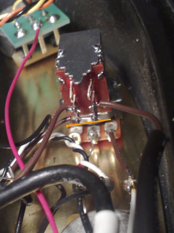
The angle of that pic is hard to tell your current wiring, especially at the push/pull switch. If you take some multiple angle shots, maybe we can help a little further.
PeteDuBaldo
Well-known member
Also, specifying which coils you are hoping to get (in each toggle position) will help a lot, too.
First off I would like to say ...Thanks a million for all you guys help. I took pics of the connections... I hope they are ok.. As far as the coils.. I originally wanted the pushed (full bridge, Full Both Full Neck) and pulled (Single inner coil, Middle inner coils, and neck inner coil). But in your diagram Pete you show that I could also have an option to have pushed (full bridge, inner coils, full neck) and pulled ( single inner coil, middle humbuckers full and neck inner coil. Is that correct.. That sounds interesting in that is sounds like it would be a little more versatile due to the more drastic tone changes. I am open to all suggestions... I play in a classic rock/Heavy Metal cover band and also write my own stuff so I like versatility. Thanks again!


 View attachment 21753
View attachment 21753Attachments
Last edited:
PeteDuBaldo
Well-known member
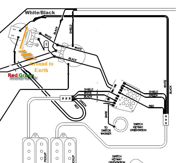
No problem, I hope we can help! I do see where there is confusion, the sounds you are looking for are not in those diagrams. My diagram shows how to change the middle position to full humbuckers when using the original EBMM JP toggle.
The standard JP wiring is
Bridge, Inside coils, Neck
The BFR JP wiring incorporates a push/pull pot.
Bridge, Inside coils, Neck
Bridge, BOTH, Neck
(There are 2 versions of this which I show in my diagram, depending on whether you want the split coil center position on the push or pull side)
If you want to wire your JP as you mentioned then it would probably be easier to start from scratch and ignore my diagram.
Bridge, BOTH , Neck
Bridge inner coil, BOTH inner coils, Neck inner coil
There are a TON of diagrams on the DiMarzio website ---- Wiring Diagrams | DiMarzio
Dr.Strangenote
Well-known member
It looks right going by the photos. I cannot see, but assume that the neck red in on the (red) PCB. What also doesn't show because it's taped, is that both neck and bridge are joined, such as the bridge should have both red and green together, then extended to reach the push/pull lug (left side-middle).
The neck should have the white/black joined together, and extended to reach the push/pull lug (right side-middle). What isn't quite working when you mention that there might be a grounding issue? no sound, noise, not actually splitting coils, etc?
The neck should have the white/black joined together, and extended to reach the push/pull lug (right side-middle). What isn't quite working when you mention that there might be a grounding issue? no sound, noise, not actually splitting coils, etc?
