• Ernie Ball
  • MusicMan
  • Sterling by MusicMan

GoKart Mozart

Well-known member
Joined
Nov 21, 2002
Messages
1,054
Location
Florence/Muscle Shoals, AL
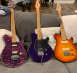
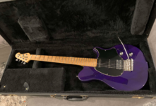
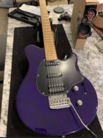
Picked up this purple Axis Sport from 1997 last week. The guy that I bought it from was able to find the original G&G with it as well, which was a bonus.

I really like how consistent the neck profiles are on these. A couple of the newer Axis and Axis Super Sports that I previously owned seemed to have a thinner profile.
1734474596033.png

1734474634527.png


L to R: 96, 97, 00

1734474657712.png


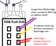
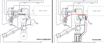
Here is where I need some wiring assistance, since someone has obviously changed some things. Factory configuration is on the left and the current state is on the right:
1734474960103.png

Guitar arrived with what looks & sounds to be a different humbucker from factory (awaiting confirmation by DiMarzio). It also has a push-pull tone pot and the switch portion wasn't hooked up when I got it. I've wired it to split the humbucker in position 1 & 3, which sound great. Here are current combinations:
Position 1 = bridge (splittable)
Position 2 = middle only
Position 3 = neck + bridge (splittable)
Position 4 = neck + middle
Position 5 = neck

I'd like to have position 2 be the middle + bridge AND let the push-pull switch still work in either position 1 or 2. Can I just run a second jumper wire from where white/black/purple meet (purple on RH diagram) and run it to the switch terminal where the white/black bridge pickup wires were in the factory configuration?

-Jacob
 
Last edited:

beej

Moderator
Joined
Aug 16, 2004
Messages
12,240
Location
Toronto, Canada
Nice score! Also that honeyburst MM90 is sweet! I have a soft spot for those sports.

I'd like to have position 2 be the middle + bridge AND let the push-pull switch still work in either position 1 or 2. Can I just run a second jumper wire from where white/black/purple meet (purple on RH diagram) and run it to the switch terminal where the white/black bridge pickup wires were in the factory configuration?

-Jacob

If you do that, when you engage the split push/pull, you'll end up with no sound at all in position 2, since you'll be grounding the lever switch.

The quick way around that is to disconnect the ground (black) wire from the push/pull, and instead run it to the top right portion of the lever switch, where the yellow wire comes in from the silent circuit and is then jumpered to the other switch positions.
  • First, remove the yellow wire from that position (position 1) and wire it instead to position 2 (the position below). Since the previous owner disconnected the bridge pickup from the Silent Circuit, this is no longer needed. Actually ... I would suggest wiring this to position 3, the position below that one, and leaving the lug in position 2 empty, so you get a noise-free combination in position 2.
  • Then, on the push/pull, remove the wire that runs to ground, and instead wire it to the lug where you removed the yellow wire (the topmost one of the 4 that were previously connected).
  • Now you can run the jumper wire from the purple on the switch to the lever switch, where it was in the factory wiring.
  • Finally, when you pull the pot, it'll ground one coil from the bridge pickup. But it'll only do this in position 1.
The more complicated way is to redo some of the wiring so that the split is done with the Silent Circuit and is noise-free, but it's probably overkill. Currently you'll get some hum in position 1 when the bridge is split.

Hope that makes sense :)
 

beej

Moderator
Joined
Aug 16, 2004
Messages
12,240
Location
Toronto, Canada
Another option is to wire it so you split to the the outer coil of the bridge rather than the inner one.

In which case:
  • Disconnect the bridge green wire from ground and wire it like the original diagram.
  • Disconnect the purple wire from the middle lug of the push/pull and wire it to the bottom lug (currently empty). Also run a jumper from that new lug to the lug on the lever switch where the B&W wires are in the original diagram.
  • Disconnect the ground wire from the top log of the push/pull and discard.
  • Disconnect the jumper on the lever switch that connects the bridge red wire from lug 1 to lug 3.
  • Disconnect the bridge red wire from the lever switch lug 1 and wire it to the top lug of the push/pull (where the ground wire was). Also run a jumper from that lug with the red wire to lug 3 on the lever switch, where the bridge wire jumper used to be.
  • Run a jumper from the middle lug of the push/pull (where the purple used to be) and run it to the lever switch, where the bridge red wire used to be.
Now, with the switch pushed in, the switching will be the same as in the original diagram. With it pulled out, you'll be connecting the split bridge back to the lever switch. Everything should be hum-cancelling.
 
Last edited:

GoKart Mozart

Well-known member
Joined
Nov 21, 2002
Messages
1,054
Location
Florence/Muscle Shoals, AL
Another option is to wire it so you split to the the outer coil of the bridge rather than the inner one.

...
Now, with the switch pushed in, the switching will be the same as in the original diagram. With it pulled out, you'll be connecting the split bridge back to the lever switch. Everything should be hum-cancelling.

As always, you are the MAN beej! Thanks so much for taking the time to write all that out and share the knowledge. I ended up going with this option #2 and am really pleased with it!

The only small deviation that I did from your directions was reverse the wires on the top & bottom terminals of the push/pull (it was splitting when pushed down and full power when pulled up when I initially rewired it this evening 🤪).


1734584317101.png

To anyone interested, I now have these selections. Great options!

Position 1 = bridge (outside coil splittable)
Position 2 = middle + bridge outside coil
Position 3 = neck + bridge inner coil
Position 4 = neck + middle
Position 5 = neck
 
Top Bottom