• Ernie Ball
  • MusicMan
  • Sterling by MusicMan

SlimBob

Active member
Joined
Jun 22, 2018
Messages
35
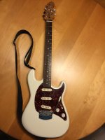
I'm looking for a 2018 Cutlass schematic - or wiring diagram - or anything that I can refer to that will guide me as I swap out the whole pickguard assembly. I wanna put the original away in a box and start using a conventional passive setup with no battery and a set of SSS stacked humbuckers. There are quite a few wires going to the jack and it could get a little confusing when it comes time to return it to original. Yes I'm replacing the jack too.

also - mine is a HSS roasted type - not sure if there is a difference in the color code or parts or pot values or whatever from year to year and HSS vs SSS vs HH etc.

THANKS!
 

DrKev

Moderator
Joined
Jul 8, 2006
Messages
7,600
Location
Somewhere between Paris, Dublin, and Buffalo
There is no difference between the 2017 schematic that I have and the wiring in my 2018 RS. PM your email address and I'll fire you the PDF.

I would suggest buying a separate pickguard. That would make everything really easy. Other than the connections to the jack and the body/trem ground, you wouldn't have to unsolder a thing on the old guard, just lift it out. Build a whole new install on the new pickguard with your new pickups.
 

SlimBob

Active member
Joined
Jun 22, 2018
Messages
35
There is no difference between the 2017 schematic that I have and the wiring in my 2018 RS. PM your email address and I'll fire you the PDF.

I would suggest buying a separate pickguard. That would make everything really easy. Other than the connections to the jack and the body/trem ground, you wouldn't have to unsolder a thing on the old guard, just lift it out. Build a whole new install on the new pickguard with your new pickups.

Yes I have a new pickguard and that's the plan. It's the jack with the multiple wires for battery switching that might get weird without a little guidance when I flipflop back to original so thank you very much I will pm with email.
 

SlimBob

Active member
Joined
Jun 22, 2018
Messages
35
Success! and thank you for the schematic - I'm sure it will come in handy when I return it to stock again. Here's my Cutlass with passive pickups - so far the jack is working flawlessly and has not cut out on me at all.
 

Attachments

  • EB-MM-Cutlass-SSS.jpg
    EB-MM-Cutlass-SSS.jpg
    47.4 KB · Views: 303

SlimBob

Active member
Joined
Jun 22, 2018
Messages
35
Nice work! What pickups did you go for?

Fender Noiseless - they were marketed as Jeff Beck Hot Noiseless Humbuckers

They are every bit as quiet as the silent circuit that comes with the cutlass. They don't have the constant presence that the buffer had but they do sound good. They were in my Strat and I liked them but the whammy on that was weird to begin with - 1984 was an odd whammy - the strings loaded from the front - the whammy was kinda worn out and impossible to find parts for. It was a USA Standard but not nearly as good a build as this Cutlass. These EB-MM are really well made instruments. I'll give it a couple of months like this and decide if I wanna put it back to original.
 

acoutron

New member
Joined
Feb 12, 2026
Messages
1
Location
switzerland
Hello,
I would like to see if there is a way to switch between the active buffer and passive mode on a Cutlass. Can someone send me the schematics please?
This Cutlass is a 2015 model, the PCB is mounted on both pot shafts. I'm sure there's a point on the board where i could interrupt the signal to bypass it to the output jack. Thanks muchly!
 

DrKev

Moderator
Joined
Jul 8, 2006
Messages
7,600
Location
Somewhere between Paris, Dublin, and Buffalo
There are no schematics for the circuit board (that's proprietary information, EBMM won't release it). And I have never seen a 2015 Cutlass circuit board (the guitar was not available to the public until 2016).

But I can tell you that on the regular production circuit boards there are pair of hexagonal pads on the circuit board in a box labelled A/P. By default those two pads are each bridged by a drop of solder. If you remove the solder from those pads the circuit goes into passive mode. BUT the circuit also has a dedicated passive outputs (the output are labelled P∆ G ∆A, each with their own ground). So you would have to wire the pads to a switch to be bridged and wire the outputs to the switch too.
 
Top Bottom