• Ernie Ball
  • MusicMan
  • Sterling by MusicMan

Amonrae

Member
Joined
Mar 28, 2014
Messages
11
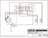
Thanks to a quick response from Music Man Customer Service, here are the switch position settings for the Albert Lee HH Guitar Center pull tap version.
I asked them because I was wondering about the middle tapped position.
I use C and E in the tapped/UP position most of the time.
I prefer A in the untapped/DOWN position (most of the time).
Volume is more consistent from one position to another when moving through the 5 tapped/UP positions.
Though I like the neck(E) in both UP and DOWN position depending on the amp and its settings, the brighter/thinner UP setting clears up a "too dark" tone nicely.
I love this coil-tap version of the guitar so much I got a second one. Both of mine have the pull pot on tone rather than volume.
A note on the schematic indicates this was used for Axis Super Sport too.

1&2 are bridge, 3&4 neck.
A= 1s2 UP/A= 1
B= 1p4 UP/B= 1p4
C= (1s2)p(3s4) UP/C= 1s(2p4)
D= 2p3 UP/D= 2p3
E= 3s4 UP/E= 4
 

SIRI

Member
Joined
Dec 28, 2019
Messages
15
I know this is old, but can anyone explain the schematic? (ie) what does A= 1s2 UP/A=1 mean?
 

xjbebop

Well-known member
Joined
Jan 8, 2013
Messages
2,793
Location
AZ High Country
Easy way to tell what's going on is to tap each coil with something metallic (small screwdriver, allen wrench, etc...) in each position while plugged in.
*each humbucker has 2 coils - one with the visible screws and one under the other side of the cover...
 

SIRI

Member
Joined
Dec 28, 2019
Messages
15
Thanks, guys!
I finally get it on Kimonostereo's EB diagram...
What's happening with my AL, is that I replaced the 5-way switch and now some of the coil (up) wiring is off, so I'm having to backtrack to find out how the coils are supposed to be connected. I thought I was ok with the schematic wiring, but something is either not wired correctly or something else isn't right.
I'm trying to piece the puzzle back together.
 

kimonostereo

Well-known member
Joined
Jul 26, 2009
Messages
1,184
Location
Honolulu, HI
Thanks, guys!
I finally get it on Kimonostereo's EB diagram...
What's happening with my AL, is that I replaced the 5-way switch and now some of the coil (up) wiring is off, so I'm having to backtrack to find out how the coils are supposed to be connected. I thought I was ok with the schematic wiring, but something is either not wired correctly or something else isn't right.
I'm trying to piece the puzzle back together.

Email customer service for the correct wiring diagram. They're your best bet. If it's a Guitar Center version, ask for that one specifically.
 

beej

Moderator
Joined
Aug 16, 2004
Messages
11,993
Location
Toronto, Canada
I have the schematic the OP is referring to. A-E were just switch positions 1-5.

"A= 1s2 UP/A= 1 " meant that in the 1st position, the bridge was in series humbucking mode (coil 1 in series with coil 2 - 1s2), and with the switch pulled up, only coil 1 (closest to the bridge) was active. Your standard coil split arrangement.

Again, with the standard coil split approach, if you ground the inside coils (2, 3) then you're not going to get any sound in position 4 where it uses coils 2 and 3 ;) Also, switch positions 2 and 3 would sound the same, since they'd both be outside coils (1, 4) in parallel.

Where I've done this (on my 25th, rewired to use the same pickup switching as the Axis SS or AL HH), I have a coil split wired up so it's only active in positions 1 and 5 (giving you split bridge or split neck). In the other positions, nothing is grounded and you get what you had before.
 

SIRI

Member
Joined
Dec 28, 2019
Messages
15
That's a whole lot to wrap around but your last example is what I'm looking for. In my case, position two, (coil tap up) is not producing sound. So I would have to investigate what's grounded with coils 1 and 4. To be honest, I'm not quite sure what grounding wire I'm looking for.
I did initially call customer service, and they sent me a PDF for the wiring (for the GC model). I think I soldered it correctly but not quite so sure if it's the right one now. Let's assume it is, is it conceivable that grounding coils can be done inadvertently and that's my issue?
 

SIRI

Member
Joined
Dec 28, 2019
Messages
15
That's it?
Anyone in for figuring out why my second position (coil tap up) might be grounding?
If this as far as I can get with the forum, I have no option than to desolder wires by guessing which might be in the wrong leg on my switch and try to figure it out that way. Trial and error...
 

beej

Moderator
Joined
Aug 16, 2004
Messages
11,993
Location
Toronto, Canada
This particular wiring scheme (the MM GC one) is different than what most people do with coil splits, to avoid having any dead switch positions. With that wiring, positions 2 and 4 are the same as they would have been before.

There's no easy way to know what you've done without looking at the wiring. You can try to post a few pics and we can take a look. But otherwise, you're probably best to take it to someone who's handy with a soldering iron and have them troubleshoot.
 

kimonostereo

Well-known member
Joined
Jul 26, 2009
Messages
1,184
Location
Honolulu, HI
Did EBMM customer service send you the diagram dated 2-10-2011 titled ALBERT LEE WITH PUSH-PULL TONE? You mentioned you replaced the 5-way switch. Did you replace it with the proper super switch (I believe it's a 5-way 4-Pole)? If the answer is yes to both of these, you might try tracing each wire one by one then marking it off on the wiring diagram. Take care to count the prongs on the switch and make sure that the right connections are made. Next, ensure all of your solder connections are good and not cold.
 

xjbebop

Well-known member
Joined
Jan 8, 2013
Messages
2,793
Location
AZ High Country
H1al6zq.jpg
 

Attachments

  • ALHHPP wiring.jpg
    ALHHPP wiring.jpg
    66.4 KB · Views: 51
Last edited:

SIRI

Member
Joined
Dec 28, 2019
Messages
15
I called them to send me the older version (thanks for that!) and the only difference is the bridge red wire (hot) being soldered to the third inner leg (discounting the end legs) instead of the second. I tried that but with the same result. The switch is from EB and a direct replacement. Is it possible I burnt through the switch? CS feels it's unlikely. I'll be checking all the joints again by chance that I cold soldered one of them.
Thanks...
 

SIRI

Member
Joined
Dec 28, 2019
Messages
15
Well, that's what happened; somehow had a cold solder involving a bare wire connecting two legs and the red wire from my pickup. Everything activates as it should but there is a slight bleed through on some positions. I'll
live with it until I get someone to check the electronics out.
 
Top Bottom