• Ernie Ball
  • MusicMan
  • Sterling by MusicMan

ffariasrey

Member
Joined
Mar 17, 2021
Messages
10
So I tried to do the push/pull mod on my 2001 JP6 non-piezo that was posted more than a decade ago:

http://forums.ernieball.com/ernie-b...ot-mod-installed.html?highlight=split+problem

Every positions seems to be working fine except for the push middle position (HH non split) which barely makes a sound.

I saw a couple of users that had this same issue and both have JP6 non-piezo. Any solution?

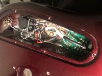
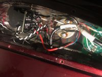
I'll leave a couple of pictures.
 

Attachments

  • IMG_0683.jpg
    IMG_0683.jpg
    92 KB · Views: 103
  • IMG_0684.jpg
    IMG_0684.jpg
    99.2 KB · Views: 91

dave1812

Well-known member
Joined
Apr 25, 2011
Messages
575
Location
Germany
There are different revisions for the JP 3 Way Toggle Switch, i'm not sure if the wiring has changed with the revisions.
my guess is that instead of "un-doing" the Middle Position Humbucker Split, you shorted the Signal to ground.
All you do with the Push/Pull Pot is to connect or disconnect the ground to one Coil of the Pickup, for both humbuckers. So you get two Singlecoils in Parallel.
It's hard to tell from your Pictures, which wire goes where. Maybe the Custom DiMarzios had a different Color Code than the current ones. Did you take a Picture of the Electronics before you did the mod?
 

ffariasrey

Member
Joined
Mar 17, 2021
Messages
10
No, I didn't took any pics before the mod. Although It was exactly as in the tutorial. The weird thing is that every position is working except the push middle, which is supposed to be both humbuckers fully engaged. As far as I know Dimarzio color code hasn't changed.

To make it clearer red and green from bridge are going to C2 from the push/pull and black and white are going to C1. Then i connected 1 and 3 from the pot and extended a cable from 3 to ground (not the pot, but the small plate in the cavity where all the ground cables go)

Furthermore, on stock middle position I'm pretty sure it was connected both humbuckers in split mode. IDK if that might be useful to identify the problem
 
Last edited:

dave1812

Well-known member
Joined
Apr 25, 2011
Messages
575
Location
Germany
that sounds like it's wired correctly.
something i just noticed on your picture, the Bridge "G" Solder Pad looks like it's bridged to the "W" Solder Pad.
that might cause a short to ground in the Middle Position.
 

dave1812

Well-known member
Joined
Apr 25, 2011
Messages
575
Location
Germany
Just to clarify, The other 3 Regular Toggle Switch Positions work as they did before the mod? Full Bridge Humbucker, Split Middle Position, Full Neck Humbucker?
what happens if you desolder the Ground Connection from "3" ?

I just wondered if the first JP Models switched the Coil Tap to Hot instead of Ground. I don't think they did though, since Petrucci's Ibanez Guitars already had this Switch Setup.
 

ffariasrey

Member
Joined
Mar 17, 2021
Messages
10
Just to clarify, The other 3 Regular Toggle Switch Positions work as they did before the mod? Full Bridge Humbucker, Split Middle Position, Full Neck Humbucker?
what happens if you desolder the Ground Connection from "3" ?

I just wondered if the first JP Models switched the Coil Tap to Hot instead of Ground. I don't think they did though, since Petrucci's Ibanez Guitars already had this Switch Setup.

No. Im trying to do the mod that in push mode humbuckers operates fully in every position of the toggle siwth and in pull mode the humbuckers operates in coil split in every position in the toggle siwtch.
 

ffariasrey

Member
Joined
Mar 17, 2021
Messages
10
I just checked the schematic i got for the JP BFR that has the Push/Pull Mod.
i think i found the issue.
Try this:
Connect the Push/Pull Contact "3" back to the 3 Way Switch "Solderpad Bridge R"
Then connect Push/Pull Contact "1" to 3 Way Switch Solderpads " Neck W&B" and bridge W&B on the Toggle Switch Circuit Board.

Sorry I'm a little confused with your explanation since I'm using a CTS pot, where 1-3 are the upper pins, C1-C2 the middle pins (which are always active) and 2-4 the lower pins. You mention that I have to connect the "contact 3" back, I assume you refered to C2

Basically you want me to disconnect C2 and solder Red cable back to the plate into the R slot? leaving the green cable in C2?

Then the other step you want me to unsolder W&B from C1 and solder them back into the plate and bridge them (W with B?

If I understood correctly only the green bridge cable would remain in the push/pull pot in the C2 pin.

Sorry, I'm a total noob in this!
 

dave1812

Well-known member
Joined
Apr 25, 2011
Messages
575
Location
Germany
No. Im trying to do the mod that in push mode humbuckers operates fully in every position of the toggle siwth and in pull mode the humbuckers operates in coil split in every position in the toggle siwtch.

Sorry, i thought you wanted the BFR Style Wiring, where the Push Pull Pot only changes the Coil Split in the Middle Position of the Toggle Switch.
This is pretty hard to troubleshoot, since it sounds like you connected it correctly.
There is something i just noticed though. Your Toggleswitch is a different Revision than the on in the other Thread you linked.
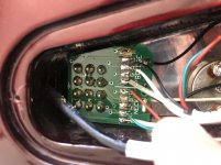
Can you take a closer Picture of the Toggle Switch Circuit Board? My guess is that you have to bridge some connections on the PCB.

Does anyone know what Rev A does differently than the Pre Rev A Switches?
 

ffariasrey

Member
Joined
Mar 17, 2021
Messages
10
Sorry, i thought you wanted the BFR Style Wiring, where the Push Pull Pot only changes the Coil Split in the Middle Position of the Toggle Switch.
This is pretty hard to troubleshoot, since it sounds like you connected it correctly.
There is something i just noticed though. Your Toggleswitch is a different Revision than the on in the other Thread you linked.
Can you take a closer Picture of the Toggle Switch Circuit Board? My guess is that you have to bridge some connections on the PCB.

Does anyone know what Rev A does differently than the Pre Rev A Switches?

Ok, sending one! thanks mate.

IMG_0686.jpg
 

ffariasrey

Member
Joined
Mar 17, 2021
Messages
10
Sorry, i thought you wanted the BFR Style Wiring, where the Push Pull Pot only changes the Coil Split in the Middle Position of the Toggle Switch.
This is pretty hard to troubleshoot, since it sounds like you connected it correctly.
There is something i just noticed though. Your Toggleswitch is a different Revision than the on in the other Thread you linked.
Can you take a closer Picture of the Toggle Switch Circuit Board? My guess is that you have to bridge some connections on the PCB.

Does anyone know what Rev A does differently than the Pre Rev A Switches?

What if I take the DPDT switch and remove the PBC and rewire everything to the switch? I know that it would look a bit more messy, but other than that I would get what I want. The following diagram should work, right? would I lose anything else besides a cleaner cavity?

https://d2emr0qhzqfj88.cloudfront.net/s3fs-public/diagrams/2h1v1PPt_split_ep1111_0.pdf
 

dave1812

Well-known member
Joined
Apr 25, 2011
Messages
575
Location
Germany
What if I take the DPDT switch and remove the PBC and rewire everything to the switch? I know that it would look a bit more messy, but other than that I would get what I want. The following diagram should work, right? would I lose anything else besides a cleaner cavity?

https://d2emr0qhzqfj88.cloudfront.net/s3fs-public/diagrams/2h1v1PPt_split_ep1111_0.pdf

you could do that of course. you can also order the switch from ebmm, that way you would only have to connect the wires to the new pcb and the mod should work fine with it.
I took the Switch out of my JP7 and made a schematic if anyone was interested. it's a Rev A PCB
 

ffariasrey

Member
Joined
Mar 17, 2021
Messages
10
you could do that of course. you can also order the switch from ebmm, that way you would only have to connect the wires to the new pcb and the mod should work fine with it.
I took the Switch out of my JP7 and made a schematic if anyone was interested. it's a Rev A PCB

Unfortunetly EBMM sell only within the US and I´m from Chile, so I´ll disconect the 4PDT and wire it as the Dimarzio diagam shows..It should be the same but less clean, I can live with that haha. Thanks mate!
 
Top Bottom