


Help! JP 6 mod with push/pull switch not working

AndreeTheG

Member
Joined
Apr 20, 2021
Messages
14
Hello everyone, I've changed the stock pups on my JP6 with Crunch Lab and Liquifire and everything works perfectly.

I wanted to add a push/pull on tone in order to have:
with push:
- full bridge
- full bridge + neck
- full neck

and with pull:
- bridge split
- bridge split + neck split
- neck split

so I followed this wiring diagram but I get no sound (when push) and split sound (when pull) when I am in middle position, I though it was out of phase maybe so I invert red and green from neck but nothing. Checked the wiring a lot of time but it's the same as the schematic. Am I doing something wrong? I've found all schematics same as this..
Thanks

744662075_10243062965732916_8053995282413164682_n.jpg
 
Last edited:
To confirm, you're wiring the Green & Red wires from the bridge pickup to the push/pull switch? And the Black and White wires from the neck pickup?
 
Ok, so no sound in the middle position, regardless of what the push/pull switch is doing.

In that case, the pickups are being grounded in the middle position, so it's something on the PCB. I would double check that none of the solder pads are making contact with adjacent ones. Use a multimeter to check the connections.

If you're sure that's not the case, then you'll have to get out a multimeter and start checking which pads are active in the various toggle switch positions.

Feel free to post a close-up picture of your wiring. Maybe there's something obvious.
 
Ok, so no sound in the middle position, regardless of what the push/pull switch is doing.

In that case, the pickups are being grounded in the middle position, so it's something on the PCB. I would double check that none of the solder pads are making contact with adjacent ones. Use a multimeter to check the connections.

If you're sure that's not the case, then you'll have to get out a multimeter and start checking which pads are active in the various toggle switch positions.

Feel free to post a close-up picture of your wiring. Maybe there's something obvious.

Thanks, basically I have no sound when is push and split sound (bridge split and neck split) when is pull. So I am only missing the push sound (full both hb).

Checked all and pads are not connected with adjacent ones except the pads of white and black of neck part but it’s on pcb stamp, default on pcb.

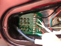
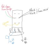
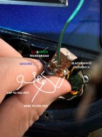
I attach the pcb and a draw of my wiring of the push/pull pot.
Thanks :)

IMG_0024.png

IMG_0025.jpeg
 
Is this a picture of your guitar? Looks like one from a thread years ago. If not, can you take a picture of your wiring, on the PCB and push/pull switch?
 
Is this a picture of your guitar? Looks like one from a thread years ago. If not, can you take a picture of your wiring, on the PCB and push/pull switch?
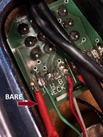
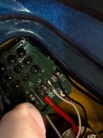
Yeah sure, it's the same, I'll attach here.
No pads on pcb are linked each other (except w+b on neck part that has a path on the pcb stamp).

I put a red rubber on bare in order to avoid contact with other components.

The push/pull is perfectly wired (as in my other guitars), I just added some wire to reach the b&w and r&g. I cannot take a full picture of the base but I draw it (it's wired like the schematic and how it was on original pot, mid with cap, external with wire to the external leg of vol. pot)

Hope You can help me :) thanks really!!

IMG_3858.JPG

IMG_3859.JPG

IMG_3860.jpg
 
So the only combination of toggle positions / coil splitting that doesn't work is the middle position with the push/pull pushed (split disengaged)? That is baffling.

With the push/pull pushed (disengaged), B&W from the neck are connected, as are R&G from the bridge. Worst-case, you'd short those out, but then you'd end up with a coil split ... and that option works. And if there were other wiring issues with the humbuckers (like R&G or B&W not properly connected), you would notice in the (N) or (B) toggle positions.

I was looking to see what revision you had of the switch PCB, but I can't tell from that photo. However, I don't think it matters. I don't have a JP but I do have a few of those switches. I checked with a multimeter and the switching is what it should be. Removing B&W from the neck and R&G from the bridge and shorting them should do what you want.

Unfortunately, this is difficult to troubleshoot remotely. I would get out a multimeter and check all of the wiring. See what connections go to output / ground in each switch position. Basically follow everything through, and see if you can find out where you've gone wrong.
 
Back
Top