• Ernie Ball
  • MusicMan
  • Sterling by MusicMan

Alex S.

Member
Joined
Nov 5, 2022
Messages
6
Location
Israel
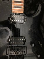
Hello everyone! Here is my story … Some time ago I bought 2021 MM BFR Luke 3 HH in black sparkle.

The guitar plays like a dream but the original MM custom wound pickups were a bit weak to my taste. In general, I decided to replace them with something else and to try DiMarzio Transitions (I'm not a big fan of ceramic pickups though).

i went to MM Customer Support (great guys!) about wiring color codes and they answered on my questions and also gave me wiring diagram for Luke 3 HH with DiMarzio Transition humbuckers. Next day i swapped the original MM humbuckers for Transitions, checked all with a dmm (according to wiring diagram) and got to my amp to hear how the new pickups sound. Everything was good in the beginning (on a clean sound). But as soon as I switched to drive or hi gain, a certain problem immediately arose. In position 2 and 4 of 5-way lever switch, when the humbuckers split into single coils that operate in parallel mode (inside and outside combinations of singles) I've got 60 hz cycle hum... It was little strange to me as i know when two singles from splited humbuckers working in parallel, it must be quiet, without 60 hz cycle hum. I looked under the hood (on pcb board) and rechecked again (according to diagram). All seems good,visually... Then I took out my other axe, also with two humbuckers (without internal preamp) and in the 2nd and 4th positions of the 5 way switch, while splitting the humbuckers into singles in parallel mode, there was absolute silence. After that, I decided to re-solder new pickups again. After finishing soldering work, I checked and rechecked with dmm and magnifying glass every (literally) wire from the pickups,5-way switch, Pu Comp and other trim pots settings, grounds wiring ,input jack,battery,everything... (of course, according to the wiring diagram from the factory). But the 60 hz noise problem, when 2 and 4 position in use (two singles in parallel combination) still exists… The humbuckers themselves, in other positions (1,3 and 5) works well.

I would be very grateful if any of you who faced such a problem could suggest how to solve it.
 
Last edited:

loocnmad

Well-known member
Joined
Oct 28, 2018
Messages
124
Just a guess but, it might be possible it's grounding the wrong side of one of the hb's. If the pickups are oriented correctly the split positions should either be both inner coils or both outer coils. Otherwise the selected singles won't be rwrp and won't "buck" the hum.

You can test it by switching to those positions and gently tapping the screws or slugs with a screwdriver or allen wrench.
 

Alex S.

Member
Joined
Nov 5, 2022
Messages
6
Location
Israel
Just a guess but, it might be possible it's grounding the wrong side of one of the hb's. If the pickups are oriented correctly the split positions should either be both inner coils or both outer coils. Otherwise the selected singles won't be rwrp and won't "buck" the hum.

You can test it by switching to those positions and gently tapping the screws or slugs with a screwdriver or allen wrench.
Yes, I did it (screwdriver tapping test on pickups)...Even before I wrote this whole story.

I installed the humbuckers the same way they are installed at the factory.Screw side of the bridge humbucker - toward the bridge and a screw side of the neck humbucker - toward the neck of the guitar (reversed- will attach pic). Also wiring color code for the new(DiMarzio) pickups-absolutely the same as for previos original MM humbuckers (i got from MM customer support original wiring diagram for the DiMarzio Transition pickup's era, especially for this guitar(Luke 3 HH). The only difference (visual) between the original MM pickups and the DiMarzios - The original ones have two rows of screws (one row on each coil) and the DiMarzios - Classic layout – one row of screws and one row of slugs(will attach pic). The pickups (also 5-way switch) in this instrument installed / soldered to PCB / active preamp, and not like in the classic layout ( pickups to 5 way switch, to pots, to input jack, etc.)- it's a bit tricky to figure out what's wrong...

When I performed "the screwdriver test" one thing pay my attention...In position 2 of 5 way switch ( outside combination of splited coils), the neck humbucker work correct- outside coil work, inside coil muted. In the bridge humbucker - outside coil works but inside coil not muted completely and very small amount of signal still present in that coil.

In position 4 ( Inside combination of splited coils ) - exactly the opposite.

Bridge humbucker – inside coil work, outside coil muted. Neck humbucker- inside coil work but outside coil not muted completely and very small amount of signal still present in that coil…

Since everything is on the PCB, I don’t really understand what is being cooked there with the signal from the pickups.

DiMarzio Transitions.jpg

Original MM Pickups.jpg
 
Last edited:

loocnmad

Well-known member
Joined
Oct 28, 2018
Messages
124
I don't have a Luke to compare but the control diagram on the product page shows the switch before the pcb. I don't think there is a silent circuit so any noise would be coming from the output of the switch.


Sounds like there could be grounding issues on the switch. Possibly some bad solder joints. I'd review the grounding scheme from the wiring diagram very carefully and maybe check with a multimeter if you have one.
 

Alex S.

Member
Joined
Nov 5, 2022
Messages
6
Location
Israel
I don't have a Luke to compare but the control diagram on the product page shows the switch before the pcb. I don't think there is a silent circuit so any noise would be coming from the output of the switch.


Sounds like there could be grounding issues on the switch. Possibly some bad solder joints. I'd review the grounding scheme from the wiring diagram very carefully and maybe check with a multimeter if you have one.
I have a Digital Multimeter(DMM) know how to use it.In this type/model of guitar(luke3) everything was solder is on the PCB board (Pickup's wiring,5 way switch,pots,etc...). like i wrote before, the wiring from the pickups not goes directly to 5 way swtch and the pots... Instead of that, the wiring from the pickups has to be soldered in a certain place on PCB, dedicated for this purpose...And from another place on the PSB, there is already wiring to the 5 Way switch ...I'll attach original wiring diagram.
The Grounding issues or some bad solder joints on the switch? Maybe...I checked and rechecked it in the past,before wrote whole the story. All the wiring from the pcb board to the switch and on the switch itself looks good and clean. What needs to be open - is open. What needs to be shorted - was shorted (according to the factory service scheme)...And I do not remember that this 60 hz hum have been present when the factory pickups were still installed. But still one thing came to my mind...If I remember correct, when the splited coils works in parallel and are reverse(oposite) polarity - in this situation will cansel 60 hz hum,right? I'll put on the table the original MM humbuckers, that was swapped for the DiMarzios, exactly the same way as they was installed on my guitar at factory and will try to determinate with multimeter the polarity of each pickup in that position.
 

Attachments

  • MC851Y LUKE 3 MM HH GUITAR WIRING DIAGRAM 202003528 (1).pdf
    206.3 KB · Views: 29

loocnmad

Well-known member
Joined
Oct 28, 2018
Messages
124
I see what you mean about the switch. Looking at the actual diagram, if you only soldered directly to the pads on the board, that would be the place to look.

Is it possible there is some extra solder that could be bridging some of the wires from the pickups?
 

DrKev

Moderator
Joined
Jul 8, 2006
Messages
7,187
Location
Somewhere between Paris, Dublin, and Buffalo
When I performed "the screwdriver test" one thing pay my attention...In position 2 of 5 way switch ( outside combination of splited coils), the neck humbucker work correct- outside coil work, inside coil muted. In the bridge humbucker - outside coil works but inside coil not muted completely and very small amount of signal still present in that coil.

In position 4 ( Inside combination of splited coils ) - exactly the opposite.

Bridge humbucker – inside coil work, outside coil muted. Neck humbucker- inside coil work but outside coil not muted completely and very small amount of signal still present in that coil…
Don't put any importance on a small amount of signal coming through on a tap test of a humbucker coil. The active coil can pickup some of the tap on the unactive coil so it is not necessary indicative of any problem in itself.

Carefully compare the wiring of the selector switch to the diagram; there may be an issue. Also check the wires from the pickups match the corresponding colors on the circuit board.
 

beej

Moderator
Joined
Aug 16, 2004
Messages
11,992
Location
Toronto, Canada
This is the kind of thing that's really hard to diagnose remotely. You sort of need to play with it- change up a few wires and see, etc.

Can you take a few pictures of your wiring? I have a LIII with Transitions, I can try to compare with what mine looks like.
 

Alex S.

Member
Joined
Nov 5, 2022
Messages
6
Location
Israel
I see what you mean about the switch. Looking at the actual diagram, if you only soldered directly to the pads on the board, that would be the place to look.

Is it possible there is some extra solder that could be bridging some of the wires from the pickups?
I checked the solder joints/pads/wires Everything is clean and nothing shorted.
 

Alex S.

Member
Joined
Nov 5, 2022
Messages
6
Location
Israel
Don't put any importance on a small amount of signal coming through on a tap test of a humbucker coil. The active coil can pickup some of the tap on the unactive coil so it is not necessary indicative of any problem in itself.

Carefully compare the wiring of the selector switch to the diagram; there may be an issue. Also check the wires from the pickups match the corresponding colors on the circuit board.
I agree with you that "an active coil can pickup some of the tap on the unactive coil so it is not necessary indicative of any problem in itself".
I checked and rechecked everything at least 3 times! Of course accordind to the factory's wiring diagram!
 

Alex S.

Member
Joined
Nov 5, 2022
Messages
6
Location
Israel
This is the kind of thing that's really hard to diagnose remotely. You sort of need to play with it- change up a few wires and see, etc.

Can you take a few pictures of your wiring? I have a LIII with Transitions, I can try to compare with what mine looks like.
It would be absolutely great !, if you can to compare with the wiring inside of your's Luke 3 with Transitions! I will be very, very grateful if you can take and post some photos from a close angle (the pics of pickups wiring/color codes sequence on the PCB board) of how it was soldered in your's guitar at the factory!!! This will help a lot, not only for me personally, but also for all the other guys who decide to replace the pickups installed at the factory with something else!!!
I also received some information from someone who probably knows what is at stake (quote): "The possible error in the factory diagram may be due to the fact that the original custom wound MM neck pickup we made for MM was identical to the Transition neck model in terms of performance, but the wiring is not the same."

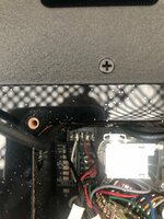
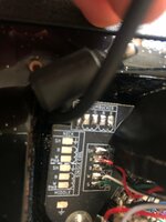
I'll add pictures (the sequence of pickups wiring/color codes,soldered on a PCB board in my axe. These pics were taken when original MM pickups were still in my guitar and before any soldering works. The difference is that I soldered more cleanly. :

Neck Pickup ( from left to right ) : Shield(black isoleted), white, green, red, black.

Bridge Pickup ( from top to down ) : Shield(black isoleted), red, black, white, green.

All soldered according factory's wiring diagram:censored:

Neck Humbucker Wiring.jpg

Bridge Humbucker Wiring.jpg
 
Last edited:

beej

Moderator
Joined
Aug 16, 2004
Messages
11,992
Location
Toronto, Canada
Hi Alex- I had a chance to look at my Luke today and I have an older version of the wiring. In my case the pickups are soldered to the lever switch which is then connected to the board. So- that won't help you.

I'm assuming the solder connections are all clean clean (they look to be), but you could always check with your meter.

My next guess, like you, would be that MM is using a different polarity on the pickups. Looking at the various wiring diagrams, the neck and bridge are wired differently. This supports what you're hearing- you would only notice it in the split positions (2 & 4).

The bridge is wired like a standard Dimarzio- R to hot, B&W tied together (or shorted for coil split), G to ground. But the neck is backward from what Dimarzio normally does- W to hot, G&R together (or shorted for split coil), B to ground.

Given that, I'd probably reverse the wiring on the neck pickup. R to the W pad, B to the G pad, W to the R pad, G to the B pad.

(Also- to find out what coils are working you can just test for continuity from the pads when the lever switch is in the right spot. Tricky to get in there, but more accurate than tapping on the coils.)

Hope that helps.
 
Top Bottom