• Ernie Ball
  • MusicMan
  • Sterling by MusicMan

dreghead

New member
Joined
Mar 15, 2018
Messages
3
hi all

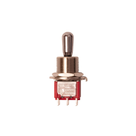
i'm trying to fix-up a steve morse standard which had a missing toggle switch. the toggle switch that was missing is the 3-way 6-pin toggle near the input jack (this is the toggle that brings the slanted pickup into the mix).

i purchased a replacement from ernie ball.

the guitar tech has the the wiring schematics, and i sent him a picture of the inside of a steve morse standard, but he's confused. one of the confusing parts is the small green PCB that appears to have 9 pins and is attached to the 3-way 6-pin toggle. i'm not electrically inclined at all, so i can't really help him.

can anyone help explain what's going on in the steve morse standard with the 3-way 6-in toggle and the 9 pin PCB? if so, i'd greatly appreciate it and i'll pass it along to the tech...
 

beej

Moderator
Joined
Aug 16, 2004
Messages
12,444
Location
Toronto, Canada
It's being used as a simple 3-way switch (on/on/on).

Basically, the output from the lever switch is wired to the top lug of this switch, rather than to the volume pot, as would normally be done. The neck single is wired to the bottom lug. Then, the middle lug is wired to the volume pot.

So- this switch is the 'gate keeper' of what goes to the guitar's output (volume pot). Flip the switch one way, you get the lever output. The other, you get just the bridge single. In the middle, you get *both* (lever + bridge single). It's pretty simple really.

If you look at the wiring diagram, you're only using three of the lugs from the PCB. It's overkill. Probably just b/c Steve liked that particular switch.

If you need a wiring diagram, PM me your email address and I can send you out. Good luck.
 

Moruan89

New member
Joined
Jan 5, 2024
Messages
1
Location
Cagliari, Sardinia, Italy
It's being used as a simple 3-way switch (on/on/on).

Basically, the output from the lever switch is wired to the top lug of this switch, rather than to the volume pot, as would normally be done. The neck single is wired to the bottom lug. Then, the middle lug is wired to the volume pot.

So- this switch is the 'gate keeper' of what goes to the guitar's output (volume pot). Flip the switch one way, you get the lever output. The other, you get just the bridge single. In the middle, you get *both* (lever + bridge single). It's pretty simple really.

If you look at the wiring diagram, you're only using three of the lugs from the PCB. It's overkill. Probably just b/c Steve liked that particular switch.

If you need a wiring diagram, PM me your email address and I can send you out. Good luck.
hello!
I’m Andrea from italy.
Sorry if something is not clear to me.
I’m having the same problem, my Morse previous owner customized the wiring and seems that in my guitar there’s a 6 pin three way toggle, but my tech support is having some problems restoring the original one.
Can I ask you for a diagram or some help?
Thanks in advance:)
 

banjoplayer

Well-known member
Joined
Jan 8, 2007
Messages
2,761
Location
Ulm, Germany
hi dreghead,
got my Morse in 2007 and at the end of the year the switch stopped working. The German distributor sent me a replacement (b/c my local dealer was not willing to do anything...)
We took the PCB, de-solered it from the broken switch and soldered it onto the new one. In my picture you can see both switches in the red circles.
It works ever since!

DSCF1132.JPG
 

GerH

New member
Joined
Mar 16, 2026
Messages
1
Location
Ireland
Hello Folks - I'm new to this Forum!

Have my SM here in Ireland since 2003. My 3-way has just begun to 'pack it in', it won't stay in the Bridge Single Only position.

I'm wondering do I need to do what banjoplayer [Hello, Germany!;)] did and desolder/resolder the PCB or can I go direct to the 3-way lugs and ignore the pcb?

Also, haven't a clue where/how to actually get a replacement toggle here - that's another hurdle to be tackled🤷‍♂️

Any advice will be greatly appreciated folks and THANKS!
 

beej

Moderator
Joined
Aug 16, 2004
Messages
12,444
Location
Toronto, Canada
Hey there- you can certainly solder to the toggle, you don't need the PCB. Just make sure the toggle actually works and isn't the culprit.

As for spare parts, you can buy them direct from mm:

That said, it's a generic switch and you can use anything you'd like.
 
Top Bottom