threeminutesboy
Well-known member
we want more !!!!

T
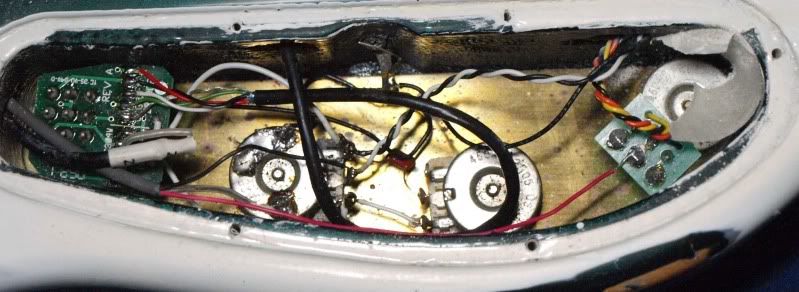
If anyone would possibly be willing to take some detailed pictures of the inside cavity of their JP BFR (I got a push pull tone pot for the JP)so I could see the wiring first hand, it'd be REALLY appreciated. I'm just not loving this diagram.
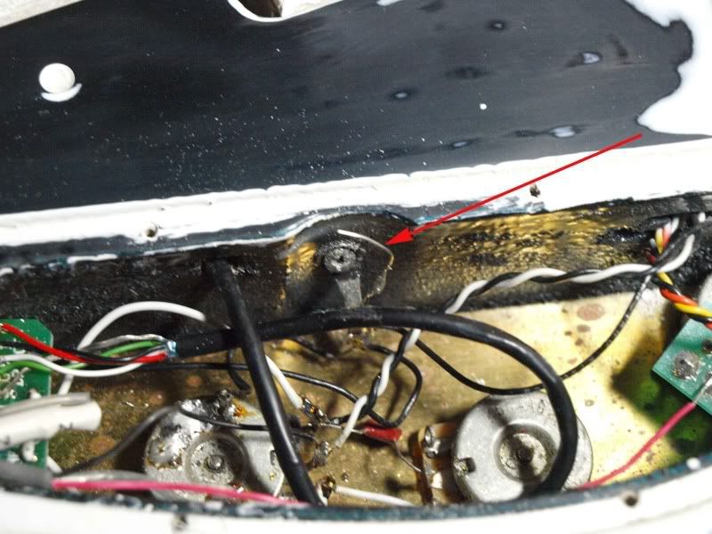


Looks like you just solder a bare wire between that pole and the pickup selector switch washer, which should be a common ground.
Someone please confirm this before he does it.
Morbid, if nobody else has done so by then, I will take pictures of one of my BFRs for you this evening.
That would also be stellar. Thank you VERY much.

I'd also volunteer for photos, but I remember that you wanted the BFR setup, right?
that thing in the diagram is a common ground point and the wire that is shown as going to the trem claw is a wire that goes into the tremolo cavity and attaches, or is soldered to, the metal piece that holds the trem tension springs. (the claw) usually the pickguards are lined with a conductive foil and the wires going to them can lay on the body and make contact when the pickguard is screwed dwon on top of it, or it is soldered to the back of a pot, or a switch which contacts the foil.
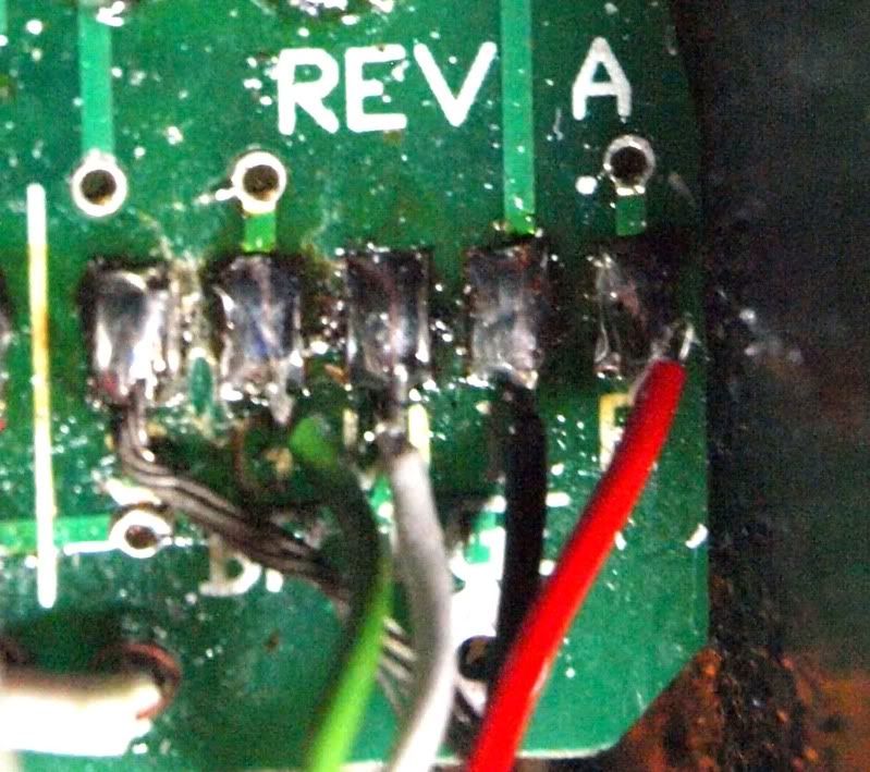
shoot nah - that is just the grounding wire for the pickup dum Spud!!
Sorry


