• Ernie Ball
  • MusicMan
  • Sterling by MusicMan

bsteff666

Well-known member
Joined
Apr 1, 2006
Messages
136
Location
Beaver, PA
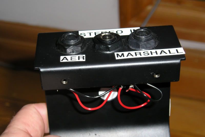
You can buy everything you need to build a splitter box on Ebay.

Here is the enclosure.
1590B Style Stomp Box Effects Pedal Enclosure US Seller Fast Shipping | eBay

You need two switchcraft mono jacks.
Switchcraft 1 4" 11 Mono Jack for Effects Guitar Amp | eBay

And you need one switchcraft stereo jack.
Switchcraft 1 4" 12B Stereo Jack Effect Pedal Output | eBay

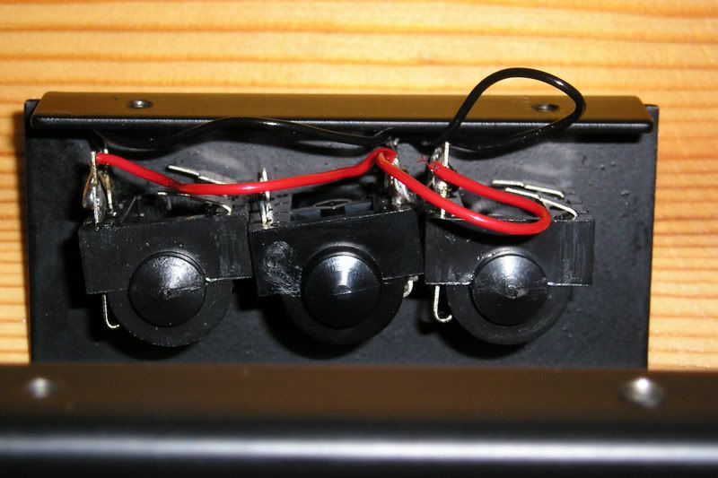
Other than that...you just need some hookup wire...the capability to drill the 3 holes in the enclosure for the jacks...and the ability to solder.

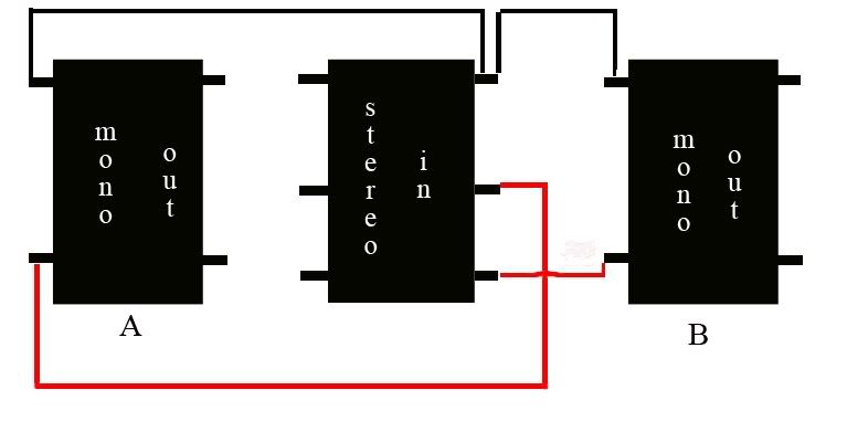
I can send you a PM & tell you how to hook it all up.
 

QuietSpike

Well-known member
Joined
Apr 5, 2014
Messages
707
Location
Coachella, CA
Does seem like the easiest option once it's set up correctly. It's just the initial setup I guess. Do you need different or extra gear for this iption to work then?


It's easy… just follow the signal…

Option A- Using one amp for both piezo and magnetic-- my signal goes regular cable from mono out of guitar to wah, to GCX in (8 loops), to loop 1 (tube screamer), to loop 2 (compressor), to loop 3 (LR Baggs DI box), to Mark V input, FX loop out back to GCX to loop 4 (modulation), to loop 5 (delay), back to FX return. Just for clarity, I have a Decimator ProRack G in there as well. Using the GCX, I can bring loops in and out with one button push on the MIDI controller… so I flip the piezo on and select the preset with the LR Baggs (and delay and/or chorus if wanted).

Option B- separate piezo and mag signals-- To me, this is easier and far more friendly sounding… Using a TRS cable (stereo) from the guitar to a splitter box-- the magnetic signal follows the ^^above^^ signal path (minus the LR Baggs, obviously). The piezo signal goes to the DI box and then to the PA (using delay/chorus in the loop of the DI box if wanted). You can also run this to a separate amp (like an acoustic amp). Now all you do is flip the piezo switch on, and you are rocking acoustic. Instead of running a TRS cable, you can run two cables to each signal path (this is pre-majesty JPs only), but this is ridiculous for live situations… just get a TRS cable and a splitter. :)

If you're playing a smaller venue, the single amp solution works best (and the sound guy/gal doesn't get too upset with you wanting to take up 4 of his channels!). If you know your sound guy/gal, or the venue is large/complex enough to support it, the second option is the way to go, IMO.


Again, as stated before, you don't *need* a DI box for either option… but it will sound more authentic/warmer/better with one.
 

Soulforged

Member
Joined
Jul 8, 2014
Messages
11
Ah right ok, so there's literally no need at all to do anything besides flip the switch on the guitar, don't even need to stomp on a switch on the board? Brilliant if that's it. Didn't realise you didn't have to use you're foot as well. One thing, why would it take up 4 channels on the desk??

I've managed to find the parts for the splitter here in the uk I think....

Stereo jack
Allparts 1/4" Stereo Jack Socket Switchcraft Nickel- Allparts - Allparts from Strings Direct UK

Mono jack
Allparts 1/4" Mono Jack Socket Switchcraft (#11) Nickel- Allparts - Allparts from Strings Direct UK

Project box
ALUMINIUM DIECAST ELECTRONICS PROJECT BOX ENCLOSURE 111 X 60 X 31MM | eBay

I have the capabilities and tools for drilling, and soldering shouldn't be a problem, will need to brush up a bit beforehand. Any particular type of wire I need to connect it all up? If you could send me the instructions that would be awesome thank you.
 

Spudmurphy

Well-known member
Joined
Aug 23, 2005
Messages
12,037
Location
Cardiff, United Kingdom
Last edited:

QuietSpike

Well-known member
Joined
Apr 5, 2014
Messages
707
Location
Coachella, CA
Ah right ok, so there's literally no need at all to do anything besides flip the switch on the guitar, don't even need to stomp on a switch on the board? Brilliant if that's it. Didn't realise you didn't have to use you're foot as well. One thing, why would it take up 4 channels on the desk??

if you're running stereo rig, and/or asking for two+ mics per cab for better blended sound... The list goes on! :) I've pissed off (american version of 'pissed') a sound guy or two in my time trying to over complicate my sound thru the PA.... in my younger days. I've learned to chill (and to have most of it ready on my end for any situation).

I have the capabilities and tools for drilling, and soldering shouldn't be a problem, will need to brush up a bit beforehand. Any particular type of wire I need to connect it all up? If you could send me the instructions that would be awesome thank you.

Yeah.... Not my area of expertise... Spud sounds way more knowledgeable on this. I hung a ceiling fan for the first time a few years ago.... That is the extent of my electrical engineering capabilities. :)
 

KEOKI

Well-known member
Joined
Jan 28, 2014
Messages
158
Location
Orlando
If you are going to try to build, or buy, one of these splitters, a ground lift is a necessary component. More important in some applications than others but the 60 cycle hum can be a deal breaker.
 

Spudmurphy

Well-known member
Joined
Aug 23, 2005
Messages
12,037
Location
Cardiff, United Kingdom
Well I certainly wouldn't disagree entirely with KEOKI, but my splitter doesn't have one. I don't think Pete Dubaldos has one either (I may be wrong) and the 6165 pedal doesn't have an earth / ground lift. The original EB splitter doesn't have one. Heck, I wouldn't even know how to include one in "my build". However some people have experienced hum problems.

Maybe we have better electrics in the UK :rolleyes::D
 

Soulforged

Member
Joined
Jul 8, 2014
Messages
11
Right, I didn't realise you were including the mics for cabs in that. I don't think I'll be experiencing any of those issues any time soon. Yeah, my electrical knowledge isn't exactly great, that's why I think I'm asking really simple questions ha.

Ok, interesting. I didn't even think of that. I have no idea how I'd do that, after a quick google, can't even find one to buy. So, if I go without one, and I do get hum, the box I listed above is surely big enough to hold a ground lift too.

@spud, if you could PM be a wiring diagram or instructions on what I need to do to make the box I'd really appreciate it. And if you have any suggestions as to what wire I need that'd be great too.

Edit. The pictures in that second link you put up don't work, they must be down. I sort of get the pictures in the first link, I think just to make sure I'll need telling which wire goes to which terminal etc, not the brightest, until I know exactly what to do.
 
Last edited:

Wahoonc

Well-known member
Joined
May 29, 2014
Messages
448
Location
D.C.
If you are going to try to build, or buy, one of these splitters, a ground lift is a necessary component. More important in some applications than others but the 60 cycle hum can be a deal breaker.

Yes, this is what I was talking about when I originally posted about piezos picking up noise. This is what I use:

Amazon.com: Seismic Audio - Passive Direct Box w/ Ground Left and Attenuator Switch DI Box: Musical Instruments

I use a y-cable, though, so don't need to split the signal. The balanced signal goes straight to an acoustic amp. The magnetic pups from the y-cable go straight to my egnater.
 

Spudmurphy

Well-known member
Joined
Aug 23, 2005
Messages
12,037
Location
Cardiff, United Kingdom
Right, I didn't realise you were including the mics for cabs in that. I don't think I'll be experiencing any of those issues any time soon. Yeah, my electrical knowledge isn't exactly great, that's why I think I'm asking really simple questions ha.

Ok, interesting. I didn't even think of that. I have no idea how I'd do that, after a quick google, can't even find one to buy. So, if I go without one, and I do get hum, the box I listed above is surely big enough to hold a ground lift too.

@spud, if you could PM be a wiring diagram or instructions on what I need to do to make the box I'd really appreciate it. And if you have any suggestions as to what wire I need that'd be great too.

Edit. The pictures in that second link you put up don't work, they must be down. I sort of get the pictures in the first link, I think just to make sure I'll need telling which wire goes to which terminal etc, not the brightest, until I know exactly what to do.
No probs - I'll see what I can do when I get home.
 

Spudmurphy

Well-known member
Joined
Aug 23, 2005
Messages
12,037
Location
Cardiff, United Kingdom
Photo 1 shows the way I had the inputs and outputs mounted on my box.
The centre socket is the stereo in socket, straddled either side by the AER (acoustic) amp socket out, and the tube amp socket out(labelled Marshall)
So a stereo lead into the centre socket splits the lead into two outputs from the box.
(that white circle in the centre, behind the red/black wires is either a redundant label, or just a reflection. It is not a component.)
Photo 1
splitter2.jpg


The next photo, Photo 2 shows what's "under the hood" - the actual wiring.
Don't worry if you are struggling to make out the wiring connections - the connections should be clearer in the final photo 3.

But lets not look at Photo 3 just yet, read the following first ....

From left to right you have:-
a Mono Jack Socket component, which has 4 lugs.
You only need two of the lugs, so, 2 are unused and I folded them down.

In the centre you have the stereo jack socket component. You can't see them all here,but it has 6 lugs and you will you only use 3 of them (why I didn't fold down the unused lugs , I don't know!!)

Then another mono jack socket component which again has 4 legs - 2 of them unused and folded down.

Photo 2
splitter3.jpg


So get your 3 components, and lay them out the same as in the photo above.

The diagram shown in Photo 3 shows a graphic representation of the same jack sockets, and how you wire the lugs used.

There are seven soldered joints in total.
- simple as that really.

Photo 3
splitter.jpg


Hope that all makes sense?
 

Soulforged

Member
Joined
Jul 8, 2014
Messages
11
Mate that's fantastic, thanks for those, makes sense to me. As soon as I have the components in front of me, I'm sure it'll make complete sense too. Will hopefully start ordering parts tomorrow. Although, I've just remembered the spares and repairs place by my work, maybe he can do me a deal on jacks.

What wire should I ask him for??

I'll post some pictures once I have it built, if I do it right and it works ha... See if it's up to scratch.


Also, is it an active DI box I'll be needing?
 

Spudmurphy

Well-known member
Joined
Aug 23, 2005
Messages
12,037
Location
Cardiff, United Kingdom
Well the wire is about the thickness of the wire used in mains 3 core cable. The core copper wire should of course be braided.
Infact the wire stripped from an old mains cable should be fine - the low amperage type like they used in the mains cable supplying power to radios (not like cooker mains cable!), but shouldn't be too thick as you may find it difficult getting heat into it from your soldering iron.

That diagram in photo 3 is further explained by the fact that the sleeve of the jack socket (Black wire) is the ground - common to all 3 sockets (see explanation of stereo jack here http://www.diyha.co.uk/electronics/stojack.html)
The "tip" of the jack feeds mono out B
and the "ring" feeds mono jack out A.

The only reason I mention this is that if you were to buy the type of sockets you have mentioned, they won't have the 4 or 6 lug configuration, so you need to have an understanding of "what part of the jack plugs mono & Stereo does what" so you can wire them up.
I can't answer your DI box question as I don't use one, maybe some DI box users could chime in here?
 
Last edited:

PeteDuBaldo

Well-known member
Joined
Jul 16, 2004
Messages
10,190
Location
Central Connecticut (Manchester) USA
Mate that's fantastic, thanks for those, makes sense to me. As soon as I have the components in front of me, I'm sure it'll make complete sense too. Will hopefully start ordering parts tomorrow. Although, I've just remembered the spares and repairs place by my work, maybe he can do me a deal on jacks.

What wire should I ask him for??

I'll post some pictures once I have it built, if I do it right and it works ha... See if it's up to scratch.


Also, is it an active DI box I'll be needing?


Yes, you want to be able to lift the ground on the XLR out from the DI. (I use the Aura Spectrum)

Overall, the DIY splitter box is fairly simple to wire. It shouldn't take more than 20 minutes start to finish, including drilling the holes.
 

QuietSpike

Well-known member
Joined
Apr 5, 2014
Messages
707
Location
Coachella, CA
You don't need an active DI box since the piezo is active, but it doesn't matter if you use an active one (the LR Baggs and Fishmans discussed here are active)-- you will just want to turn the gain way down to keep it under control.
 

Soulforged

Member
Joined
Jul 8, 2014
Messages
11

Soulforged

Member
Joined
Jul 8, 2014
Messages
11
sorry, i've just noticed it says switched jack....what's that exactly, is that right or should i be using unswitched?
 
Top Bottom