So this weekend I performed a "simple" wiring mod to my Sterling 5 HS. I was never using position 2 (counting from the bridge) on the switch which is coil 1 and the phantom coil, basically the bridge single coil soloed. To me this sound was thin and quiet compared to the other switch positions. I originally wanted to rewire position 2 to give me coils 1&2 in parallel, for more of a Stingray type tone. But after some digging, I found out that the bridge humbucker in the HS model only has 3 conductors (compared to the H model which has 4) so this humbucker can't be wired in parallel.
So I decided to rewire position 2 with coils 1&3 in parallel. Not surprisingly, this position now sounds like a jazz bass. To me it's a lot more usable of a tone than the bridge single coil by itself. It's a pretty mellow tone compared to the otherwise aggressive sound of the Sterling, but I like it and it makes the bass even more versatile. And this position is still hum-cancelling (it's essentially the same as position 3, but using the phantom coil instead of coil 2 to cancel the hum).
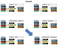
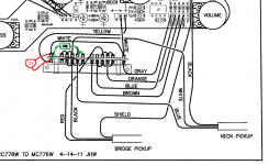
To perform this mod, locate the 5 lugs in the upper-left quadrant of the switch on the wiring diagram (these correspond to switch positions 1 through 5, RIGHT to LEFT) . Remove the jumper that joins lugs 1 and 2 (counting from the right), insert a jumper between lugs 2 and 3 (counting from the right), and disconnect capacitor 102 from the 2nd lug (leaving it only connected in position 1). I've also included a block diagram of all the switch positions. Now coil 3 (which is the white lead from the neck pickup) is connected in positions 2, 3, 4 and 5.
I say this was a "simple" mod because there are really only 3 solder joints that need to be changed. But I put "simple" in quotes because it was a lot of work to remove the stock jumper that went between positions 1 and 2 - it was a single core wire that was tied around the lugs before it was soldered. I tried for a while to desolder it, but I ended up just cutting a corner off of each lug to get it off.
I also experimented with capacitor 102 to see its effects on the tone of the bass. I deduced from the circuit diagrams that whatever pickups go into the yellow input on the board are wired in series with whatever goes into the white input. But in positions 1 and 2 from the factory, that capacitor 102 is goes from the yellow to the white input. While I had it off I tried it in all of the pickup positions, and I discovered that when it's connected it rolls off the highs a little and makes the bass sound more aggressive. I liked it and was tempted to connect it to all of the positions and leave it permanently on, but I decided to just keep it in position 1 (bridge HB) because I didn't want to change the stock tones of positions 3, 4 and 5.


