• Ernie Ball
  • MusicMan
  • Sterling by MusicMan

bvdrummer

Well-known member
Joined
Aug 7, 2014
Messages
91
Location
The OC
So this weekend I performed a "simple" wiring mod to my Sterling 5 HS. I was never using position 2 (counting from the bridge) on the switch which is coil 1 and the phantom coil, basically the bridge single coil soloed. To me this sound was thin and quiet compared to the other switch positions. I originally wanted to rewire position 2 to give me coils 1&2 in parallel, for more of a Stingray type tone. But after some digging, I found out that the bridge humbucker in the HS model only has 3 conductors (compared to the H model which has 4) so this humbucker can't be wired in parallel.

So I decided to rewire position 2 with coils 1&3 in parallel. Not surprisingly, this position now sounds like a jazz bass. To me it's a lot more usable of a tone than the bridge single coil by itself. It's a pretty mellow tone compared to the otherwise aggressive sound of the Sterling, but I like it and it makes the bass even more versatile. And this position is still hum-cancelling (it's essentially the same as position 3, but using the phantom coil instead of coil 2 to cancel the hum).

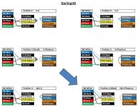
To perform this mod, locate the 5 lugs in the upper-left quadrant of the switch on the wiring diagram (these correspond to switch positions 1 through 5, RIGHT to LEFT) . Remove the jumper that joins lugs 1 and 2 (counting from the right), insert a jumper between lugs 2 and 3 (counting from the right), and disconnect capacitor 102 from the 2nd lug (leaving it only connected in position 1). I've also included a block diagram of all the switch positions. Now coil 3 (which is the white lead from the neck pickup) is connected in positions 2, 3, 4 and 5.

I say this was a "simple" mod because there are really only 3 solder joints that need to be changed. But I put "simple" in quotes because it was a lot of work to remove the stock jumper that went between positions 1 and 2 - it was a single core wire that was tied around the lugs before it was soldered. I tried for a while to desolder it, but I ended up just cutting a corner off of each lug to get it off.

I also experimented with capacitor 102 to see its effects on the tone of the bass. I deduced from the circuit diagrams that whatever pickups go into the yellow input on the board are wired in series with whatever goes into the white input. But in positions 1 and 2 from the factory, that capacitor 102 is goes from the yellow to the white input. While I had it off I tried it in all of the pickup positions, and I discovered that when it's connected it rolls off the highs a little and makes the bass sound more aggressive. I liked it and was tempted to connect it to all of the positions and leave it permanently on, but I decided to just keep it in position 1 (bridge HB) because I didn't want to change the stock tones of positions 3, 4 and 5.
 

Attachments

  • Wiring Mod.jpg
    Wiring Mod.jpg
    73.3 KB · Views: 4,133
  • Sterling HS 4-14-11.pdf
    47.4 KB · Views: 466
  • cfd_sterling_hs.pdf
    28.4 KB · Views: 400

sanderhermans

Well-known member
Joined
Nov 5, 2013
Messages
1,091
Location
belgium
Good job! Mayebe some sound clips? I am afraid that there wont be manny fans here for moddig an ebmm...
 

bvdrummer

Well-known member
Joined
Aug 7, 2014
Messages
91
Location
The OC
Haha yeah. I just moved a couple of wires though...it's not like I put in an aftermarket preamp or something! I'll try to upload clips when I get a chance.
 

agt

Well-known member
Joined
Aug 1, 2007
Messages
1,541
Location
The grand Ball room (CA)
Resurrecting this thread ...

Thanks for sharing this. I would be interested in hearing any sound examples!

Does anyone have any idea if a similar mod can be done to the HH version for position 3 to get just 1&3 as opposed to 1&3+2&4?
 

Meypelnek

Well-known member
Joined
Oct 17, 2013
Messages
156
Location
Munich, Germany
I don't think it will work. I have once had managed 1+4+2 (Position 2) what sounded great. And I guess it won't be a problem to get 1&3+2 (in Position 3).
 

bvdrummer

Well-known member
Joined
Aug 7, 2014
Messages
91
Location
The OC
I don't know if it's possible. EB will probably give you the wiring schematics, but they wouldn't tell me what's going on inside the board. I think I had the H and HS wiring diagram and it still took me a while to deduce what was going on with the yellow/white inputs to the board. On the H, there is a third input to the board (black) where on the HS that is not connected. It will also depend on if the HH pickups are 3 or 4 conductors.

In all honesty this mod wasn't worth it because the output level in position 2 is much lower than the others, so I still don't ever use it.
 

Thegrandwazoo

Active member
Joined
Nov 1, 2014
Messages
27
Location
West By-God Virginia
So this weekend I performed a "simple" wiring mod to my Sterling 5 HS. I was never using position 2 (counting from the bridge) on the switch which is coil 1 and the phantom coil, basically the bridge single coil soloed. To me this sound was thin and quiet compared to the other switch positions. I originally wanted to rewire position 2 to give me coils 1&2 in parallel, for more of a Stingray type tone. But after some digging, I found out that the bridge humbucker in the HS model only has 3 conductors (compared to the H model which has 4) so this humbucker can't be wired in parallel.

If these basses had a 4-wire pickup, what would be the way to go about your initial plan? In other words, I'd like to swap in a 4-wire aftermarket pickup and have both bridge-series and bridge-parallel as a switch option. Position 2, I find, is useless to me. Nearly inaudible, and if I do crank everything til it can be heard, very weak and brittle-sounding, so what you had intended to do at first would be awesome for me.

Truthfully, I don't personally use any switch positions but 1 and (rarely) 3. In hindsight, I probably should've bought a single-pickup Sterling, but I thought the HS would serve me better (it doesn't). I'd sell it and get a single H, but this bass is special to me plus it has a quartersawn neck and either pau ferro or the reddest, most highly figured rosewood fingerboard I've ever seen. Also, while most of the best-playing basses I've ever handled have been EBMM Sterlings, mine is by a considerable margin the sweetest yet, so getting rid of it is pretty much out of the question. I appreciate any help you can offer.
 
Last edited:

bvdrummer

Well-known member
Joined
Aug 7, 2014
Messages
91
Location
The OC
If these basses had a 4-wire pickup, what would be the way to go about your initial plan? In other words, I'd like to swap in a 4-wire aftermarket pickup and have both bridge-series and bridge-parallel as a switch option. Position 2, I find, is useless to me. Nearly inaudible, and if I do crank everything til it can be heard, very weak and brittle-sounding, so what you had intended to do at first would be awesome for me.

Truthfully, I don't personally use any switch positions but 1 and (rarely) 3. In hindsight, I probably should've bought a single-pickup Sterling, but I thought the HS would serve me better (it doesn't). I'd sell it and get a single H, but this bass is special to me plus it has a quartersawn neck and either pau ferro or the reddest, most highly figured rosewood fingerboard I've ever seen. Also, while most of the best-playing basses I've ever handled have been EBMM Sterlings, mine is by a considerable margin the sweetest yet, so getting rid of it is pretty much out of the question. I appreciate any help you can offer.

The way EB wired this is so unusual to me since they have a series combination happening inside the board!. Like I said in my OP, I did deduce that whatever goes into the white input on the board gets combined in series with whatever goes into the yellow input.

This part in curly braces is purely speculation because I'm not a wiring expert, I just stared at this thing forever until I saw a pattern. {I think the stock bridge pickup in the HS may be wired with the green (ground) coming out between the two coils, and the two coils themselves are 180 out of phase, but the phase of one is inverted in the board.} You could check this theory by measuring the DC resistance from red-green, and then from black-green. You would have to make this measurement with the pickup disconnected from everything.

There are 3 inputs on the board (black, white & yellow). The single H model uses a 4 conductor pickup and uses the black input, where on the HS there is no connection to the black input on the board. EB gave me the wiring schematics but they wouldn't tell me what's going on inside the board. Looking at that may help.

Alternatively, if you get a 4 coil pickup you can combine your coils 1&2 in parallel before going into the board, similar to the position 2 (mod) in my figure except using coils 1&2 instead of 1&3. You'd just have to be careful with matching the polarity of your new pickup with the neck pickup to keep the hum cancelling properties and not have out of phase signal.
 
Last edited:

Thegrandwazoo

Active member
Joined
Nov 1, 2014
Messages
27
Location
West By-God Virginia
Oh, I see. Well, that sounds a bit more involved than I'm completely comfortable getting, and also partially explains why I was so flabbergasted by what I was looking at when I took the control cover off this morning to poke around, haha! Can you tell me a bit more about this 'capacitor 102'? I found it on my bass, and if it rolls off highs and is used in position 1, it may be the source of/cure for nearly all of my problems. I believe it may be the reason my position 1 is much quieter than the other multi-coil positions.

How would I go about connecting it in all switch positions? In the future I may even want to put a mini toggle in to disable it should I wish to. That seems more within my capacity, I don't really want to change pickups and all that garbage anyway, the factory one sounds awesome, and the 1&2 in parallel sound isn't all that important to me if all else was equal. I still wouldn't use the second notch, but I don't care.
 
Last edited:

Thegrandwazoo

Active member
Joined
Nov 1, 2014
Messages
27
Location
West By-God Virginia
I also experimented with capacitor 102 to see its effects on the tone of the bass. I deduced from the circuit diagrams that whatever pickups go into the yellow input on the board are wired in series with whatever goes into the white input. But in positions 1 and 2 from the factory, that capacitor 102 is goes from the yellow to the white input. While I had it off I tried it in all of the pickup positions, and I discovered that when it's connected it rolls off the highs a little and makes the bass sound more aggressive. I liked it and was tempted to connect it to all of the positions and leave it permanently on, but I decided to just keep it in position 1 (bridge HB) because I didn't want to change the stock tones of positions 3, 4 and 5.
^talking about this.
 

bvdrummer

Well-known member
Joined
Aug 7, 2014
Messages
91
Location
The OC
Oh, I see. Well, that sounds a bit more involved than I'm completely comfortable getting, and also partially explains why I was so flabbergasted by what I was looking at when I took the control cover off this morning to poke around, haha! Can you tell me a bit more about this 'capacitor 102'? I found it on my bass, and if it rolls off highs and is used in position 1, it may be the source of/cure for nearly all of my problems. I believe it may be the reason my position 1 is much quieter than the other multi-coil positions.

How would I go about connecting it in all switch positions? In the future I may even want to put a mini toggle in to disable it should I wish to. That seems more within my capacity, I don't really want to change pickups and all that garbage anyway, the factory one sounds awesome, and the 1&2 in parallel sound isn't all that important to me if all else was equal. I still wouldn't use the second notch, but I don't care.

I have highlighted the stock position of Capacitor 102 on this wiring schematic in green. I'm not sure how familiar you are with this type of 5-way switch. There are 4 "quadrants" to the switch. In each quadrant, the outermost lug is connected to one of the 5 adjacent lugs that depends on the switch position. You can see that in the upper left quadrant, the capactor is connected to lugs 1 and 2, and it connects to the lower left lug. You can also connect it to any of the other lugs 3, 4, or 5 in that quadrant if you want. Or if you want it in all 5 positions you could just connect it straight to the output lug as I have drawn in red.

It would be easy to put a mini toggle to turn it on/off too. Just need a single pole switch that either connects the capacitor or leaves the connection open.

However, I don't recall this capacitor affecting the overall volume too much. It just seemed to make the bass a little more growly and less bright sounding, kinda similar to using a little overdrive. I did like the tone it gave, but I figured I'd rather use a pedal than to permanently make the bass sound like that.

I think where EB was trying to balance the volume among the 5 positions is in the lower right quadrant of the switch, with the blue, brown and orange wires. They all go to different resistors on the board, and the blue one connects to positions 1, 3 & 4 (all positions with 2 or more coils on). Positions 2 and 5 here use different resistors and that might have been an attempt to balance the volumes, but yeah I agree position 2 is still too quiet.

In the end I still mostly use positions 1, 3 & 4, and I've learned to adjust the 3 band EQ to make their volumes similar. For position 1 I turn up the bass a little. For positions 3 and 4 I turn the bass down, boost mids, and turn the treble down maybe 50%.

Capacitor 102.png
 
Last edited:

Thegrandwazoo

Active member
Joined
Nov 1, 2014
Messages
27
Location
West By-God Virginia
That's all it would take? Wow, that's pretty easy. In answer, I'm not at all familiar with this type of switch, but that seems to be pretty straightforward. I would've thought I needed a single-pole double-throw switch to toggle it on and off, but if I just need to make/break that connection, I see that a single-pole should do it. Maybe it's not responsible for the volume difference between positions 1 and 4 (I realize 2 and 5 can't help but have lower output and 3 higher due to different numbers of coils), but it's worth a look to me. It may be that the darker, low mid-heavy timbre fools my ears into thinking it's quieter, but I don't think so since position 4 has a lot of booty, too. Thank you for all your help! I'll experiment with it and see what I come up with.
 
Top Bottom